


07 Oct Identifying defined & robust testing

There is currently no test standard providing a robust set of proven and well researched tests to assess the performance capabilities of video flame detectors (VFD) and video smoke detectors (VSD) in anticipated service environments. To assess video fire detectors, sufficiently detailed and well demonstrated benchmark tests for basic performance are required, here raman chagger, Principal Consultant (Fire Safety) at BRE Global shares the findings of a collaborative research programme which set out to achieve this.
Video fire detectors are increasingly being used to detect fires in areas where traditional detectors may be inappropriate, or where a quicker response is needed or visual verification required. Due to their complex and variable functionality, there are no defined and robust methods of assessing their capabilities for testing and certification purposes.
It was with this in mind that BRE Global, together with the Fire Industry Association (FIA) and video fire detector manufacturers, formed a research group with the aim of developing the following four tests:
- VFD – bench testing,
- VFD – full-scale fire testing,
- VSD – bench testing,
- VSD – full-scale fire testing.
As well as demonstrating the repeatability of the test methodologies, the opportunity of assessing the performance of VFD and VSD against the four proposed tests were also taken. Two different VFD and three VSD systems were used in this work. The methodologies that were developed, the detector responses and the performance criteria that have been proposed for these, are explored in the following sections.
VFD – bench testing
The point-type flame detector standard, EN 54-10:2002, was used as the basis for developing benchmark tests for VFD. This proved to be challenging due to the differences in the detection algorithms used to detect the presence of a flame. The same test method could not be used to assess the two VFD systems investigated in this research, because they used different methods of identifying flame signatures.
Using either a real, steady (un-flickering) flame or a looped video of a flame as a stimulus, and varying the distance, D, of the camera from the stimulus, has proven to be an acceptable method of producing VFD responses. These methodologies can then be used to assess the performance of the VFD and establish whether the responses from a number of samples is within the required spread. The maximum, mean and minimum responses are referred to as Dmax, Dmean and Dmin.
The spread requirements from EN 54-10:2002 are Dmax : Dmean ≤ 1.15 and Dmean : Dmin ≤ 1.22. These apply for the VFD systems tested as the Dmax : Dmean and Dmean : Dmin ratios for VFD system 1 were 1.11 and 1.16 respectively, and for VFD system 2 were 1.09 and 1.06 respectively.
It should be noted that these different test methods were developed for the two VFD systems tested and may not work for other types of VFD.
VFD – full-scale fire testing
As with VFD bench testing, EN 54-10:2002 proved to be an appropriate basis for developing suitable fire tests. This standard requires two fire tests, n-heptane (see Figure 1) and methylated spirits, to be performed at fixed distances of up to 25m from flame detectors. Eight point-type flame detectors are required to alarm within 30 seconds of exposure to the fire.
This methodology was reproduced but, due to the ability of VFD to detect fires at greater distances, the tests were performed at the BRE site with up to 100m between the fires and VFD. The results demonstrated that testing in the same way as point-type flame detectors delivered comparable results for VFD. The VFD tested would repeatedly detect both fires at 35m before 30 seconds elapsed.
It is therefore proposed that the exact methodology and requirements used for fire sensitivity testing in EN 54-10 are used – but allow for greater distances – and that all tested samples should alarm at the claimed maximum distance within 30 seconds for both test fires.
VSD – bench testing
Fundamentally, VSD systems monitor a series of images taken from a video sequence to identify when the changes represent a sufficient growth in smoke to indicate a fire. To develop a test method, a simple metric was needed that reflected the amount of growing smoke within a video sequence, which could be used to determine the response characteristics of the VSD.
A metric was identified that reflected the amount of pixel change within a series of images. This was the root mean squared error (RMSE) deviation, which is the most basic way in which VSD work. This deviation is quantified by calculating the colour difference between initial and subsequent frames of a video, by looking at the attributes and changes in each pixel and then averaging them.
A smouldering cotton fire was created in the BRE fire test room and videoed with the reference camera. By comparing subsequent frames of the video with the initial one, a graph of RMSE change with time was generated that was gradually increasing linearly. When this video of the fire was played back to a VSD facing a display monitor, it would effectively “see” the same growth in RMSE. As there is a gradual increase in RMSE, the response of the VSD system can be determined by noting the time into the video at which it responds, and using the data from the graph to equate this to an RMSE response (in %).
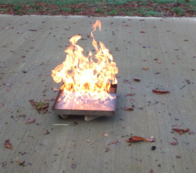
Figure 1: n-Heptane test fire in a 330mm square steel tray. When performing the tests outside, consideration needs to be given to the effects of wind and the resulting changes in the fire.
A number of different samples of each VSD system were tested and the ratio requirements from smoke detector standards (EN 54-7 and EN 54-20) of the spread were taken. These are Max:Mean ≤ 1.33 and Mean:Min ≤ 1.5. For the three different VSD systems tested the Max:Mean ratios achieved were 1.05, 1.18 and 1.07, whilst the Mean:Min ratios achieved were 1.03, 1.20 and 1.02.
Producing videos with a linear growth rate of smoke, performing RMSE analysis and then projecting videos back to cameras under correct conditions, has proved to be an acceptable method of determining VSD responses. There was no evidence that the refresh rate of the monitor adversely interfered with the refresh rate of the camera.
It is therefore proposed that the above methodology is used, and the limits from the EN standards are applied, for assessing the bench performance of VSDs.
VSD – full-scale fire testing
The full-scale fire tests for VSD were performed at the BRE Hangar in Middlesbrough, which is 40m long, 10m high (pitched roof) and 20m wide. Three VSD were configured approximately 1.5m from the floor and in close proximity to the reference camera, with all devices located 35m from the test fires. The background conditions were tightly controlled to prevent external factors such as sunlight contributing to RMSE changes.
The fire tests were performed in a chimney that shielded the light produced from the fire, but allowed fresh air to enter and smoke to escape. A large plasterboard screen was used behind the chimney, and the screen was illuminated with light from four Xenon floodlights to produce ~20 lux over the surface (see Figure 2). Modified test fires from EN 54-7 were used with TF2 smouldering wood and TF3 smouldering cotton producing white smoke, and the TF4 polyurethane foam and TF5 flaming n-heptane producing black smoke. The exact specification of fuels used for the fires can be found on the BRE website by searching for video fire detectors.
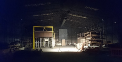
Figure 2: Test set-up with the black background screen
The optical zoom of the reference camera was used to provide a field of view that encompassed the top of the chimney and the entire screen. A video recording of the test was made and, after the test was completed, it was cropped to include only the area of interest. It was also “topped and tailed” to include the test from start to finish – the start being when the fuel was first ignited or when the power to the hotplate was switched on, and the end was when smoke production ceased.
The video sequences were then analysed and the RMSE calculated using the method described previously. This proved to be a suitable methodology for generating RMSE profiles of full-scale fires, and the VSD demonstrated the ability to respond to the smoke from these fires. An example in Figure 3 shows the RMSE changes with time for four flaming polyurethane fires (producing black smoke), with tests 1, 3 and 5 being performed against a white background and test 15 being performed against a black background.
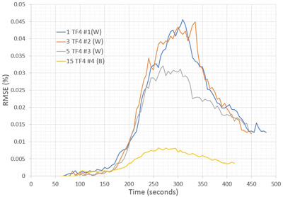
Figure 3: Profiles of RMSE from the reference cameras for all the TF4 fires
With regards to the RMSE responses of the four fires against different backgrounds, it was observed that the TF4 and TF5 fires against a black background produced 24% and 16% respectively of the RMSE when performed with a white background.
The VSD responded to all the test fires, however, the responses were quite variable between VSD. The VSD operated with an average 58% success rate for contrasting background fires and overall responded with ~52% success rate to the more challenging condition of smoke against backgrounds similar in colour to that of the smoke.
The VSD have proven their ability to respond to the smoke from these fires, despite a very low RMSE being observed on the reference camera from the small amounts of smoke generated 35m away. However, further work is required before a final methodology can be proposed for assessing their absolute performance capabilities.
Conclusions
Video fire detectors
No single bench test method was identified that could be applied to both VFD types tested, as they appear to use quite different methods of detecting the presence of a flame, and so two test methods have been proposed.
Assessment criteria taken from the point flame detector standard EN 54-10:2002, appeared to be appropriate and the VFD responded within these limits.
The fire test methodology used in EN 54-10:2002 was proposed for VFD and worked for the two different VFD tested. The methodology permits test samples to be located at distances of up to 100m from the test fires, and the VFDs tested were capable of responding at 35m with an alarm condition within 30 seconds of ignition.
Video smoke detectors
A repeatable bench test method was developed for VSD which works with both systems tested. This method involves taking a video of a developing fire, calculating the RMSE of the video sequence and projecting this video sequence to the VSD under test.
Assessment criteria taken from the point smoke detector standard EN 54-7:2001, appeared to be appropriate and the VSD responded within these limits.
During the fire tests it was observed that, despite the significant decrease in RMSE with black smoke on the black background, the VSDs had a similar success rate to that with the white background. However, in order to develop a methodology for assessing absolute performance further work is required to:
1) improve the contrast for TF2 and TF3 fires against a white background,
2) slightly slow down the growth of the TF4 and significantly slow down the growth of the TF5 fire,
3) identify why there is a difference in reported RMSE to the same fire from different cameras located in close proximity to each other.
The knowledge gained during this research work will support the various standardisation processes and contribute to the future development of related standards and codes. BRE and the FIA are working together with manufacturers of video fire detectors to identify any additional areas requiring research in this respect.
The Briefing Paper: The development of test methods to assess video flame and video smoke detectors can be read in full here https://files.bregroup.com/research/Video-Fire-Detection_2019-May.pdf